







TVC FAQs
ACVV Regulator MKII – Incorrect Stopping Sequence
- Adjust potentiometer DLT1 and DLT2 to obtain correct sequence (DLT1 is used to drop the Brake which should happen before the Mains contactors drop controlled by DLT2. DLT2 should 0.5 – 1.5 seconds after Brake has dropped.
- Check DC Bias is setup correctly. The DC output voltage when the motor is running at contract speed under load should be approximately 0 – 2v DC. The adjustment can be made on ACR8/9 B card pot marked DC Bias.
- Motor Thermistor operated (Allow machine to cool and check for cause of overheating).
- Motor Thermistor not in circuit (if thermistor is not used link CON8-5 to CON8-6 or TH1 and TH2 on terminal rail).
- Wrong phase sequence or missing phase. Also check Thyristor fuses HF1-HF3 and control fuses F1-F5.
- Phase unbalanced- Check gate leads if found to be ok suspect Thyristor open circuit.
- Motor Fault- Check line to line voltage at motor if balance check current on each phase is also balanced. If current is unbalanced suspect a motor winding fault.
- Possible short circuit or earth fault. (Disconnect U V W and check wiring also check motor for fault)
- HF2 -HF3 Blown (suspect Diode or Thyristor in DC bridge circuit short circuit)
- HF1-HF2-HF3 Blown (suspect faulty Thyristor/s between R-U, S-V or T-W)
- Check motor feedback device
- Check Brake and Brake Circuit
ACVV Regulator MKII – FDR Tripping with T
- Check motor feedback device
- Check Brake and Brake Circuit.
- Possible fault with Thyristor or Control board seek advice from TVC customer support.
Which manuals relates to ACVV Regulator MKII?
- Wrong phase sequence or missing phase. Also check Thyristor fuses HF1-HF3 and control fuses F1-F5.
- Motor Thermistor operated (Allow machine to cool and check for cause of overheating).
- Motor Thermistor not in circuit (if thermistor is not used link CON8-5 to CON8-6 or TH1 and TH2 on terminal rail).
- Phase unbalanced- Check gate leads if found to be ok suspect Thyristor open circuit.
- Motor Fault- Check line to line voltage at motor if balance check current on each phase is also balanced. If current is unbalanced suspect a motor winding fault.
- Possible short circuit or earth fault. (Disconnect U V W and check wiring also check motor for fault)
- HF2 -HF3 Blown (suspect Diode or Thyristor in DC bridge circuit short circuit)
- HF1-HF2-HF3 Blown (suspect faulty Thyristor/s between R-U, S-V or T-W)
ACVV Regulator MKIII – FDR Tripping with T
- Check motor feedback device
- Check Brake and Brake Circuit.
- Possible fault with Thyristor or Control board seek advice from TVC customer support.
- Check motor feedback device
- Check Brake and Brake Circuit
- Adjust potentiometer DLT1 and DLT2 to obtain correct sequence (DLT1 is used to drop the Brake which should happen before the Mains contactors drop controlled by DLT2. DLT2 should 0.5 – 1.5 seconds after Brake has dropped.
- Check DC Bias is setup correctly. The DC output voltage when the motor is running at contract speed under load should be approximately 0 – 2v DC. The adjustment can be made on ACR8/9 B card pot marked DC Bias.
Which manuals relates to ACVV Regulator MKIII?
UPS – COVER CORE 6-10 kVA User Manual
UPS – COVER NGS 10-30 kVA User Manual
Quick guide to turn on/off the COVER UPS JR series
- Check Output current (Above or close to full rated current).
- Monitor #4.19 accumulative current level (trips @100%).
- Reduce Current
- Check Balance
- Check Encoder
- Instant output overload, check for short circuit motor Remove Load U, V, & W.
- Diode check should be carried out the output stage of drive
Check drive for loss of Direction input or Enabled input
If replacing a motor encoder on a permanent magnet machine (i.e Endat encoder) then ropes will have to be lifted and a rotational auto-tune will be required. When replacing an incremental encoder on an induction motor a static auto-tune would in most cases be sufficient.
Please refer to job contract manual for relevant auto-tune procedure.
- Changes to drive parameters must be manually saved otherwise they will be lost after power-down.
- Navigate to the beginning of any menu which will have a number followed by 00 i.e 1.00 or 2.00.
- Press ‘M’ until the cursor flashes on the value (which will be 0).
- Using the keypad change this 0 to 1000 and press M followed by the red reset button. The 1000 will then change back to 0. This indicates that the parameters have been saved. If the value of 1000 does not change back to 0 then the save has not been successful, repeat the process. To confirm parameters have saved, power down the drive i.e turn off mains isolator, UPS if fitted and disconnect any backup batteries. Then reinstate the supply and check the last parameter edited.
Note: DO NOT change parameter 0.48 or 11.31 as this will default the drive parameter file.
- Set parameter 3.24 to 1
- Set parameter 3.40 to 0
In order to return the drive mode back to ‘closed loop’ set the following parameters.
- Set parameter 3.24 to 0
- Set parameter 3.40 to 1
These are hardware faults, drive must be removed. Please contact TVC to discuss options for replacement.
Please refer to relevant contract manual for full description of these trips but here are some common causes.
Check the following:
- Brake is lifting correctly. (Check Brake and Brake Circuit).
- Lubricate car/counterweight guides.
- Check for stiction in car/counterweight guides.
- Check motor encoder wiring.
- Possible faulty motor encoder.
- Excessive Accel/Decel rates.
- Check motor encoder coupling.
- Check Brake Apply Delay #D05 Is Not Set To Zero (Default 500ms)
- Check Drive Current #J22 Is Not Above motor rated current #B02
- Check #B16 Is Set to Maximum
- The Error is Between Profile Speed #J39 & Actual Speed #J40. Check Gains i01 i02 Starting Gains, i06 & i07 Running Gains, Distance Error Can be monitored in #J56
- Check encoder is in Feedback Mode #C14
- This could also be a balance issue
- Check #F27 is set back to D03
- If replacing a Motor Encoder on a Permanent Magnet Machine (i.e Endat Encoder) we would recommend a rotational autotune is carried out. However, a Static tune can also be carried out, but it is advisable to do it 3 consecutive times. Making sure the learnt Phase Angle C.13 on each attempt come backs with a value less a couple degrees deviation.
- When replacing an Incremental Encoder on an Induction Motor a Static Auto-Tune would in most cases be enough. Please refer to job contract manual for relevant auto-tune procedure.
- Change parameter C.14 from Feedback to Sensorless (Do Not Change The Control Mode To Open Loop A.02 or B.01).
- Change parameter C.21 Bit 0 (First Bit on Right) from 1 to 0. This will disable the Encoder Wire Break Detection. If left enabled the drive will report an Encoder 2 trip error.
- It’s important an Autotune is carried to optimise motor control prior to running the lift on Test.
- The parameter changed should be saved, however they will need to be set back to TVC default values once the encoder is fitted
- Changes to drive parameters must be manually saved otherwise they will be lost after power down
- Navigate to the beginning of any menu which will have a letter followed by 00 i.e A.00 or E.00
- Press ENTER (button above Red button) until the cursor flashes on 00
- Using the keypad Navigate UP and select SAVE PARAMETERS then press ENTER, followed by the Red Reset Button. The text SAVE PARAMETER will then change back to 0. This indicates that the parameters have been saved. To confirm parameters have saved, power down the drive i.e turn off mains isolator, UPS if fitted and disconnect any backup batteries. Then reinstate the supply and check the last parameter edited.
- Navigate to the beginning of any menu which will have a letter followed by 00 i.e A.00 or E.00
- Press ENTER (button above Red button) until the cursor flashes on 00
- Using the keypad Navigate UP and select SAVE PARAMETERS then press ENTER, followed by the Red Reset Button. The text SAVE PARAMETER will then change back to 0. This indicates that the parameters have been saved. To confirm parameters have saved, power down the drive i.e turn off mains isolator, UPS if fitted and disconnect any backup batteries. Then reinstate the supply and check the last parameter edited.
- Follow this link to Nidec Website where it can be downloaded https://acim.nidec.com/drives/control-techniques/products/ac-drives/elevator-drives. Please note you will need to register before access is allowed to download the manual.
- An APP is available for download IOS and Android (Control Techniques Diagnostics Tool) that has frequently asked questions and a troubleshooting guide.
- Dial into the EM-181 emFONE using a Mobile Phone or Landline Telephone Handset.
- Enter the following command #1239#71* The EM-181 will respond with “Sequence Accepted”.
- Please call TVC Technical Support to confirm health check telephone number. Once you have this number enter the following command #1239#4 followed by the health check telephone number and enter *. Example #1239#4XXXXXXXXXX* The em-181 will respond with “Sequence Accepted”.
- Enter the following command #1232#703* The EM-181 will respond with “Sequence Accepted”
- Ring TVC Technical support and ask for the site to be added to CMS Anywhere, Site name, End User & Phone number is required.
- TVC will confirm the site has been added and the site is reporting to Autodialler Health Check.
- Please call TVC Technical Support to confirm healthcheck telephone number. Once you have this number enter the following command via the EM1 keypad #1239#4 followed by the healthcheck telephone number and enter *. Example #1239#4XXXXXXXXXX* The EM1 will respond with “Sequence Accepted”.
- Via the Keypad enter #1239#71* The EM-1 will respond with “Sequence Accepted”.
- Via the Keypad enter #123#850* The EM-1 will respond with “Sequence Accepted”.
- Via the Keypad enter #1232#703* The EM-1 will respond with “Sequence Accepted”.
- Ring TVC Technical support and ask for the site to be added to CMS Anywhere, Site name, End User & Phone number is required.
- TVC will confi rm the site has been added and the site is repor? ng to Autodialler health check.
- Click “Configure” and enter “123” as the password.
- Scroll down to “Reporting Enable” press Enter and select 1, press Enter to Accept.
- Scroll down to “Reporting Number” press Enter.
- Please call TVC Technical Support to confirm health check telephone number. Once you have received this enter the number and press Enter.
- Scroll down to “Reporting Frequency” press Enter.
- Enter 3 and press Enter.
- Ring TVC Technical support and ask for the site to be added to CMS Anywhere, Site name, End User & Phone number is required.
- TVC will confirm the site has been added and the site is reporting to Autodialler Health Check.
All the data the EMU Mini transmits is displayed on TVC’s CMS Anywhere, which access would have been provided once installed.
The rating for the EMU Mini is IP2X
Yes
No, the EMU Mini can be installed to monitor any equipment which uses a ON/OFF Input
The EMU Mini can operate between 0 ºC to +40 ºC
The EMU Mini has stopped transmitting Data or has lost internet connectivity.
The EMU Mini varies in input voltages, these voltages range from the following:-
12v, 24v, 110v & 240v ac/dc
Yes, TVC can supply a 4G Router with Data SIM
The EMU mini requires either a Solid Line Broadband Connection or a 4G Broadband Connection
24vdc
105mm x 90mm x 60mm
- Check toolbox and faults list (exclamation mark! will be displayed next to the fault).
- Reset fault by selection event, this will show current value tripped and new value reset.
- Depress toggle to reset.
Different types of faults may require higher level of log-in, passwords and access levels are in the Ethos 1 user manual.
- Check fault logger.
- View current events, this will display faults. Events or any services that have been selected.
- Check home screen and mode this will scroll the events across the screen.
Ethos 1 User Manual
- Check lock circuitry.
- Check processor MC, MUP and MDN inputs for voltage present, input bridge failure.
- Check laser.
- Check laser power supply.
- Check handwind 43 unit LUR/LDR, possible input bridge failure.
- Check bootswitch is in bottom position (left hand side of the Ethos processor). This can also display lift out of service on the indicators.
- Check pilot relays for direction.
- Check contactor drop out circuitry (back making contacts)
- Check STR, BKR and MC contactors
- Possible issues with internal batteries on power on reset, internal battery requires replacement by TVC at the factory.
- Check CAN loom between the Ethos 1 and the VCOM.
- Check pins on cable.
- Check dipswitches and termination resistors if fitted.
- Check correct software is fitted to to Ethos 1 and VCOM.
- Technician ABCDEF
- Service 123456
Where can I get the Ethos 1 manual?
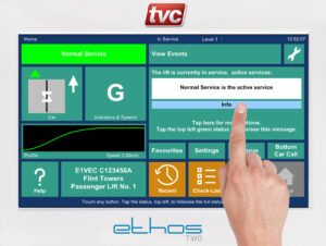
- Tap on Info panel as show below.

- CAN 1- check Group Network connections and terminators. The event can all be logged on group contracts if a processor is reset.
- CAN 2 -check Car Network connections and node board terminators. Nodes can be viewed via View IO on the Home Screen. Then using the up and down scrolling arrows you can view the status of the node boards. Green signifies node Online and Operational, Amber Network Faults, Red No Comms / Node Missing.
- CAN 3 – check Shaft Positioning Encoder wiring refer to drawings (Limax or Governor CAN encoder).
- CAN 4 (on ETSD Card if fitted)- check Absolute Encoder wiring refer to drawing.
- CAN 5 (on ETSD Card if fitted) -check Landing Network wiring and that the line terminator is fitted refer to drawing.
- From the Home screen select the Profile button (above Help) then select Adjust. In the top left-hand corner of the screen select Active Profile. The Low Energy option can then be adjusted to your given speed required.
- From the Home screen select the Check-List button and under Adapt select Secure Openings. You then have the option to secure Car and Landing Calls for any given floor.
- Tap on Solution and use the chevron buttons to scroll through the current events/ problems that are keeping the Lift out of service. Some events may need to be manual reset, these will display a reset button.
- Recalibrating the screen is the most like cause. Please refer to TVC Ethos Two Manual or select HELP option via the Ethos Two Home Screen for the procedure.
- Recalibration via the dipswitches located to the left-hand side of the touch screen, SW4 Dipswitch 2 on, reset mmi via reset push located on the rear of the board behind SW4, follow procedure displayed on screen.
Ethos Two Controller User Guide
- From the Home Screen select the Spanner button then select date and time.
- The passcode is 222222.
Where can I get the manual for Ethos Two Processor?
Ethos Two Controller User Guide
- Refer to TVC Ethos Two Manual TVL 351 Chapter 12 Traction Lift Installation Guide
Every 3 years (from installation date)
3 hours
245mm x 102mm x 53mm
390mm x 135mm x 62mm
Yes, via a UPS
4 Wire Bus (as per emFONE)
EN81-72 & BS 9999:2008
Flush (Standard Offering)
Yes
99 landings
An additional power supply is required for every 8 landings.
24vdc
Euro Key (Standard Offering)
What installation and quick start manuals are available for Ethos Navigator HCD?
Installation and quick start manuals are available for Ethos Navigator HCD
- TVL339 Ethos Navigator In-Car Information Display Installation
- TVL338 Ethos Navigator User Quick Start
- TVL337 Ethos Navigator Browser Quick Start
- TVL334 Hall Lantern and Gong Node Board Installation
- TVL333 HCD DIP Install Sheet
Isopropyl alcohol or similar IT screen cleaner
- Check Tapehead signals are being seen by the Processor and in the correct sequence.
- Check Magnet alignment and Tapehead Guide Shoe for wear.
- Check Trailing Cable and replace were necessary.
- Consecutive attempts at relevelling can also generate this event, if the processor does not see the magnets in the correct sequence. Check Valve block and Oil temperature.
- Possible Hardware Fault with Processor Consult TVC Support Customer Service.
Check the limit has been reset. The lift should be returned to the bottom floor. Then check the processor is seeing LU LD DZ and TFR (BFR should be off if limit is normally closed). The processor should now acknowledge the ECS button and clear down event.
Default Pin code is 0000 (Master Pin code 6595)
Check the processor is seeing DOL or DCL. If not check the 110vac control circuit MS feed.
Possible processor EMC noise spike ensure all contactor/relay coils and 3 phase door motor windings are suitably suppressed as per contract drawings. Also ensure the control panel has adequate earth bonding.
Check 5vdc power supply. This supply must be a minimum of 5 vdc under load. If this cannot be achieved with the existing power supply, then a replacement 5v PSU can be purchased from TVC.
I need a manual for the Hylogic Processor
I need the Ethos Two Limax33CP Setup Guide (ETSL feature only)
Take the lift to the Main Floor and cycle door.
Refer to contract drawings, a site visit by TVC can be carried out to investigate, contact TVC for further advice.
Ensure all contactors/relay coils have suitable suppressors fitted as per site drawings. Check and improve earth bonding continuity throughout installation.
Switch off mains supply, remove all processor board and clean PCB edge connectors with suitable electrical contact cleaner before firmly re-inserting them.
If this fails to rectify the issue then a site visit by TVC is recommended to investigate.
- . Check M6808 PSU supplies are outputting the correct voltage.
- Switch off mains supply, remove all processor board and clean PCB edge connectors with suitable electrical contact cleaning fluid before firmly re-inserting them. If the loop LED is still not looping/flashing following this action then it likely there is a board fault. Contact TVC customer support for further advice.
I need the manual for M6808 processor
- Check dip switches are set correctly on CPU card.
- Check BFR and TFR operation
- Check operation of door limits
Check LPF and CPF (simplex) group panels check interlinking wiring and fuses on all controllers.
Check processor inputs LU and LD for correct sequence on later versions of M6809, check LU DZ, LD sequencing to processor.
Return lift to main fire floor and cycle doors, processor should reset.
Check operation of reset limits BFR and TFR, check DIP switches on CPU card are set correctly, check door limit signalling.
Processor has seen a stepping signal in the wrong position whilst running, check SPX signal, check operation through direction contacts
Check lock circuit, check main contactors for operation, check door operation.
Processor has attempted to pilot open the doors (OC) after a short delay and door zone not energising this will be logged, check operation of limits, check operation of door contactors, check pilot relays.
Check loop LED to see if flashing, possible issues with CPU card and logic voltages.
Loss of logic supply to processor, check 10VDC supply, visual monitor 5V LED located at the tope left of motherboard.
I need manuals for the M6809 Processor
M6809 Microprocessor Manuals
LU, DZ, LD are monitored by the processor if three consecutive journeys to the same floor log a code 34 leveller direction error a multi head erro will be logged, check processor signalling from shaft equipment, tape head etc.
Landing lock is still present after the doors have fully opened, locks are assumed to be bridge, check lock circuit, landing doors, car gate and door operation
Car doors have been held continuously for 15 seconds or more, check safety edges, cabling and detector box.
- After three unsuccessful attempts to move the lift the processor reopens the doors and parks, check main contactors and relay input signalling MC and Direction Inputs.
- Pre-lock failures, check lock circuit door operator for operation
On arrival at a terminal floor the processor has reset its position as it does not correspond with the top and bottom floor, indicating the lift was out of step.
The processor is not seeing the correct levelling sequence LU, DZ and LD direction dependent.
The security code is 1234 MASTER CODE 6595
I need the manual for Onix Microprocessor Collective Lift Control?
Onix Manuals
- TVL195 Onix Microprocessor Collective Lift Control Manual
- TVL212 Onix MKII Hydraulic Microprocessor Manual
- TVL213 Onix MKII Traction Microprocessor Lift Control Manual
- TVL226 Onix MKII Traction Microprocessor Lift Control manual Gates Application
- TVL230 Onix Evolution Microprocessor Lift Control Manual Traction for Power Doors
- TVL232 Onix Evolution Microprocessor Lift Control Manual Traction for Manual Gates
- TVL233 Onix Evolution Microprocessor Manual Hydraulic
- TVL235 Onix Evolution Microprocessor Control Manual Hydraulic for Manual Gates
- TVL275 Onix Evolution Microprocessor Lift Control Manual for Bucher Hydraulic VVVF Powered Doors
ON RECEIPT OF THE UPS
· Please check for damage. Please inform TVC of any damage is found.
· This is to be fitted in a clean dry and dust proof location.
PLEASE NOTE
- The UPS must have 300mm clear space behind the ups exhaust port (fan) for ventilation.
- The dry contact card should be configured and wired as per TVC diagram and slotted in to the expansion slot on the rear of ups. Also check R.E.P.O jumper is fitted to rear of UPS (remote emergency power off )Please check range of ups as not fitted to all (default off , as set by manufacturer).
- UPS wiring should be of a suitable type and be rated to the same size cable as the TVC mains and motor wiring in the panel. Suitable glands should be fitted to protect cable entry into the UPS .Isolate mains supply and UPS supply and verify before any works are carried out.
- Mains isolator should be checked for an additional pole to disable ups auto rescue when mains isolator is manually switched off.
- Before powering on UPS the wiring should be checked that the terminals are wired correctly, US1,US2, US3 for input and US4,US5,US6 for output . If wired incorrectly this will damage the UPS.
See attached instructions for further information.
Ziehl Abegg Drive Speed Selection?